
Parametric models · practical guides
Build an enclosure from a board measurement record
Measure the board envelope and interfaces first. This reference model is a starting geometry, not support for a particular board brand.
Download these original sample files directly. Creating models, checking files and AI edits in PurCad use the credit terms shown before each paid action.
Files
Open the SCAD workspace, upload model.scad as the main source, change a parameter and compile. Compare the dimensions, then download the STL from that successful build.
Download these original sample files directly. Creating models, checking files and AI edits in PurCad use the credit terms shown before each paid action.
Parameters to check
| Parameter | Value | Checked endpoint values |
|---|---|---|
board_length | 60 mm | 40 / 100 |
board_width | 40 mm | 25 / 80 |
wall_thickness | 2.4 mm | 1.6 / 4 |
lid_clearance | 0.4 mm | 0.2 / 1 |
Default mating dimensions
| Interface | Default geometry, mm |
|---|---|
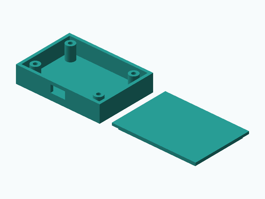
| Enclosure body (length × width × height) | 68.8 × 48.8 × 14 |
| Post centres (X, Y) from the outer front-left corner | (8.4, 8.4); (8.4, 40.4); (60.4, 8.4); (60.4, 40.4) |
| Connector cutout (width × height) | 12 × 6 |
Geometry evidence
Model file bounds, including any arranged parts: 147.6 × 48.8 × 14 mm.
A displayed model and its dimensions are geometry evidence, not proof of physical fit, strength, electrical clearance, or print success.
Build measurements (JSON)Make a board measurement record
Record board length, width, thickness, each mounting-hole center from one chosen origin, connector envelopes, and the clearance needed above the tallest component. A photo can help document orientation, but it does not replace a known scale and direct measurements.
Place posts and openings from the same datum
Keep hole centers and connector cutouts tied to one origin. Change lid clearance as its own parameter and inspect the rebuilt body and lid; do not infer physical connector fit from the viewport alone.
Separate geometry checks from fit checks
Compare the exported geometry with the measurement record, then use a low-cost fit sample for posts or a port opening. A printed sample is still not evidence that every component, cable, or material combination will work.
Questions this page answers
How do I make a box for my PCB dimensions?
Measure the board envelope, thickness, and keep-out areas from one datum. Enter those values in a source model, rebuild it, and compare the resulting inside space with the same measurement record.
Where do I put mounting posts when the board has no drawing?
Measure or trace the board, choose a stable origin, and record hole centers relative to it. Verify the locations against the board before treating the enclosure as ready to print.
How do I locate a USB-C or connector cutout?
Measure the connector envelope and its center or edge offsets from the board datum. Leave an intentional clearance and check it with a small physical sample; the model cannot confirm plug access by itself.
How can I change the lid clearance without changing the whole case?
Use a source model where lid clearance is independent of the board envelope. Rebuild and inspect the body and lid, then test the chosen clearance in your material and printer settings.