
Parametric models · practical guides
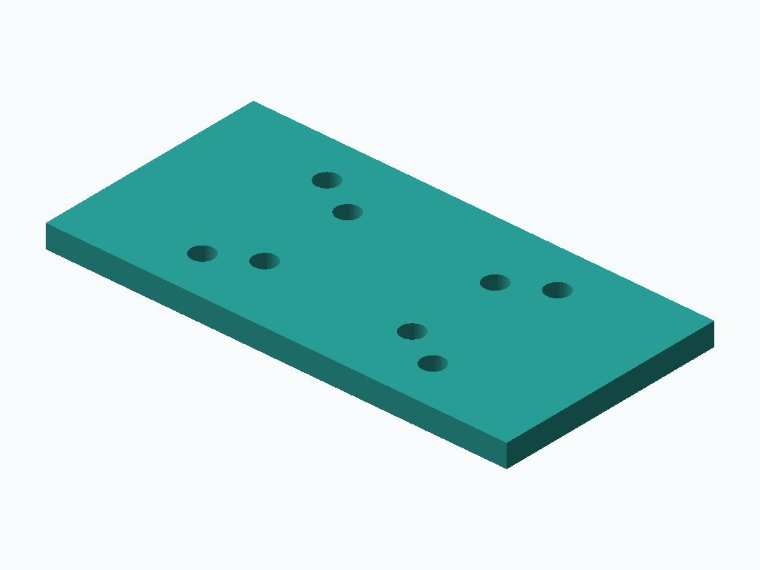
Connect two measured hole patterns
Treat each hole pattern and the arm geometry as separate constraints. This is geometry guidance, not a strength rating.
Download these original sample files directly. Creating models, checking files and AI edits in PurCad use the credit terms shown before each paid action.
Files
Open the SCAD workspace, upload model.scad as the main source, change a parameter and compile. Compare the dimensions, then download the STL from that successful build.
Download these original sample files directly. Creating models, checking files and AI edits in PurCad use the credit terms shown before each paid action.
Parameters to check
| Parameter | Value | Checked endpoint values |
|---|---|---|
plate_length | 100 mm | 64 / 120 |
plate_width | 50 mm | 40 / 90 |
source_pattern_spacing | 32 mm | 20 / 44 |
target_pattern_spacing | 50 mm | 46 / 80 |
Default mating dimensions
| Interface | Default geometry, mm |
|---|---|
| First mounting pattern (X × Y spacing) | 32 × 20 |
| Second mounting pattern (X × Y spacing) | 50 × 30 |
Geometry evidence
Model file bounds, including any arranged parts: 100 × 50 × 5 mm.
A displayed model and its dimensions are geometry evidence, not proof of physical fit, strength, electrical clearance, or print success.
Build measurements (JSON)Use a repeatable datum
Measure hole centers from one reference edge or origin. Record which face and orientation the dimensions describe, so the pattern can be checked after a revision.
Keep interface constraints independent
The two patterns may move relative to each other while their own spacing stays fixed. Check hole centers and edge clearance in the rebuilt model; validate load and fastening separately.
Questions this page answers
Can I create a drilling guide from hole spacing and edge offsets?
Yes, when both hole centers and the locating edge are measured from one datum. Test positioning on scrap before drilling a finished part.
How do I keep repeated holes aligned across several pieces?
Reuse the same source datum and hole-spacing parameters for each part. Compare the generated centers with your measurement record.
How can a bracket connect two different mounting patterns?
Model each pattern independently, then define the offset between their datums. The resulting geometry does not establish whether the bracket is strong enough for a given load.
Which dimensions must stay fixed when I change a bracket arm?
Keep the mounting-hole centers, reference edges, and required clearances fixed unless the mating interface changes. Change the arm as a separate parameter and remeasure the output.